Learning IEC 61499 and EcoStruxure Automation Expert
This lab can be performed in class during a pre-booked lab session (one per student) or at home.
Objectives
- Getting a hands-on experience on EcoStruxure: how to create, compile, test, and modify a basic function block type.
- Learning how to use an instance of a basic function block type in a composite function block type.
- Testing and debugging basic function blocks and IEC 61499 applications.
- Executing distributed remote application (FLASHER).
Expected outcome
Demonstrate the ability of running distributed applications in EcoStruxure Automation Expert.
Submission
This lab guides you through the process of creating and running several function block applications within the solutions Tutorial and Flasher. Upon completion of the lab, you will need to submit the resulting solutions via MyCourses, first archived using EcoStruxure and then combined into a single ZIP archive.
Installation of EcoStruxure
Installation of EcoStruxure Automation Expert software in Windows is supported by the corresponding installer packages. Please download and install the tool. The tool works only on Windows.
Function Block Architecture: basic artifact
Creating a new basic function block type in EcoStruxure
In EcoStruxure, one cannot simply create a function block type, but only within a solution that is a structure analogous to a project in other programming environments. Let us create a new solution. In the New Solution window, you can choose “EcoStruxure Automation Expert - Full Solution (Windows HMI)” and name it ‘Tutorial’ as shown in Figure 1(a), and click ‘Finish’ after you’ve enter your information (it might require to create a user with login and password) in the prompt ‘Properties’ window. Next in the solution explorer tree on the left, right click on ‘Basic’ and select ‘New Item’ from the context down menu as shown in Figure 1(b). In the prompt dialog assign name ‘X2Y2’ to this function block type.
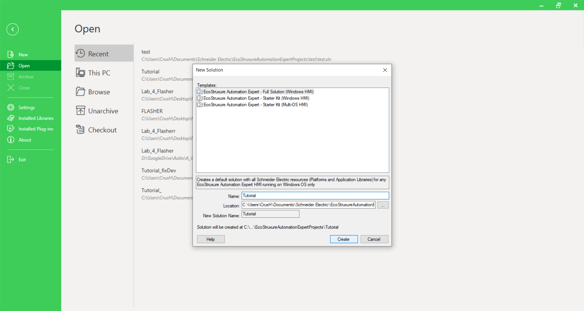
Figure 1(a). Creating a new solution.
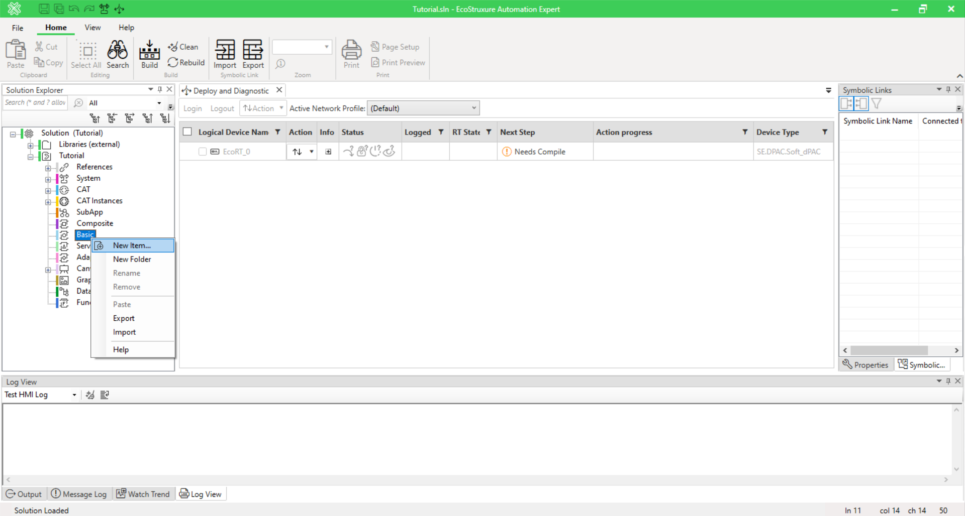
Figure 1(b). Creating a new basic function block type in the Solution Overview.
In Figure 2 (a), you will see the function block type ‘X2Y2’ created with a set of standard event and data interfaces. Figure 2 (b), we deleted event input ‘INIT’ and event output ‘INITO’, and renamed data input QI and QO to X and OUT, and changed their types to REAL.
We then add one more input Y, also of type REAL. To create an association between an event input/output and data
input/output, click on the field “With” of the event you want to create an association for and select the relevant variables in the prompt window. Do this for the input Y as shown in Figure 2 (c).
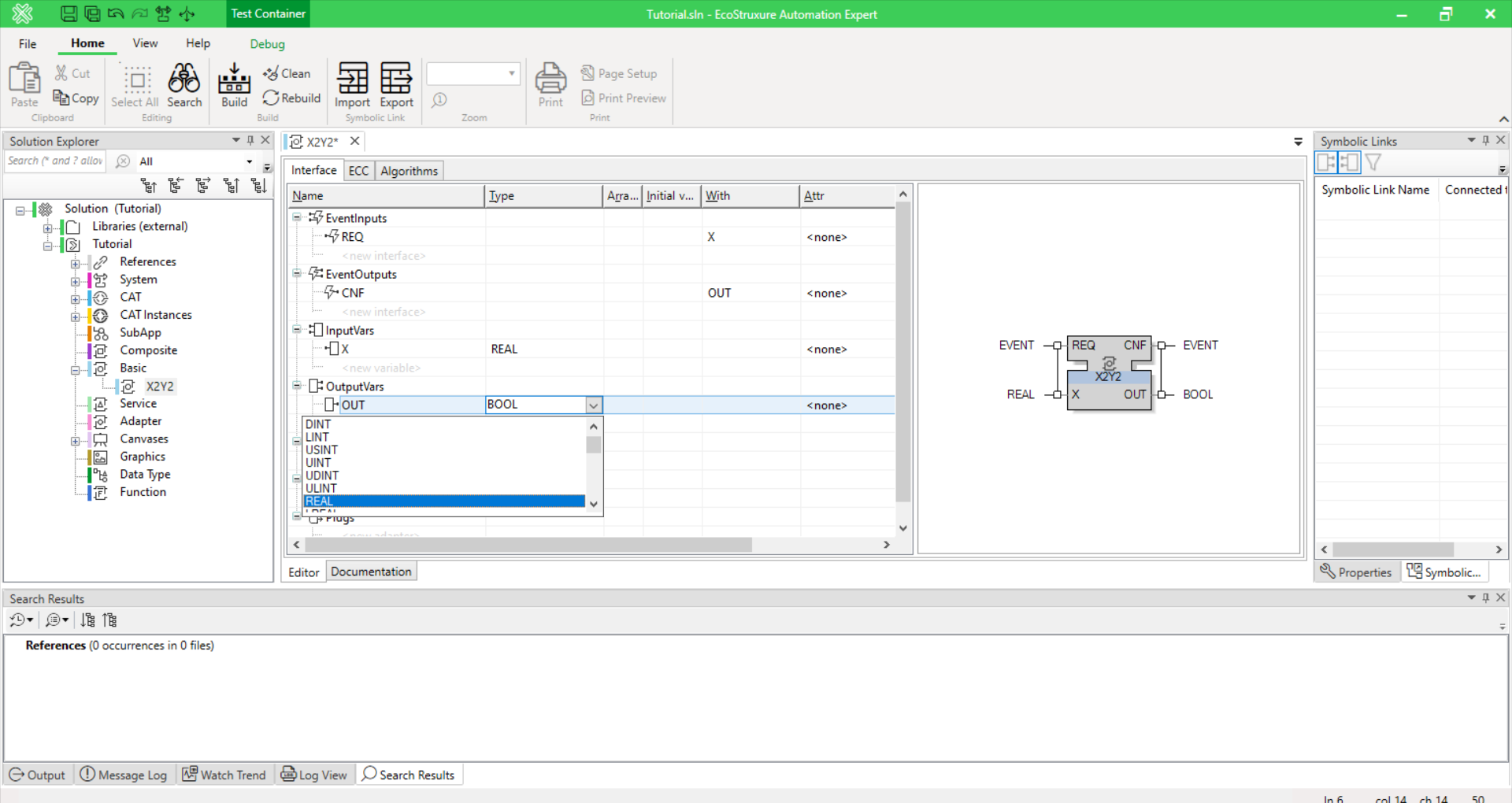
Figure 2(a). Creating ‘X2Y2’ function block.
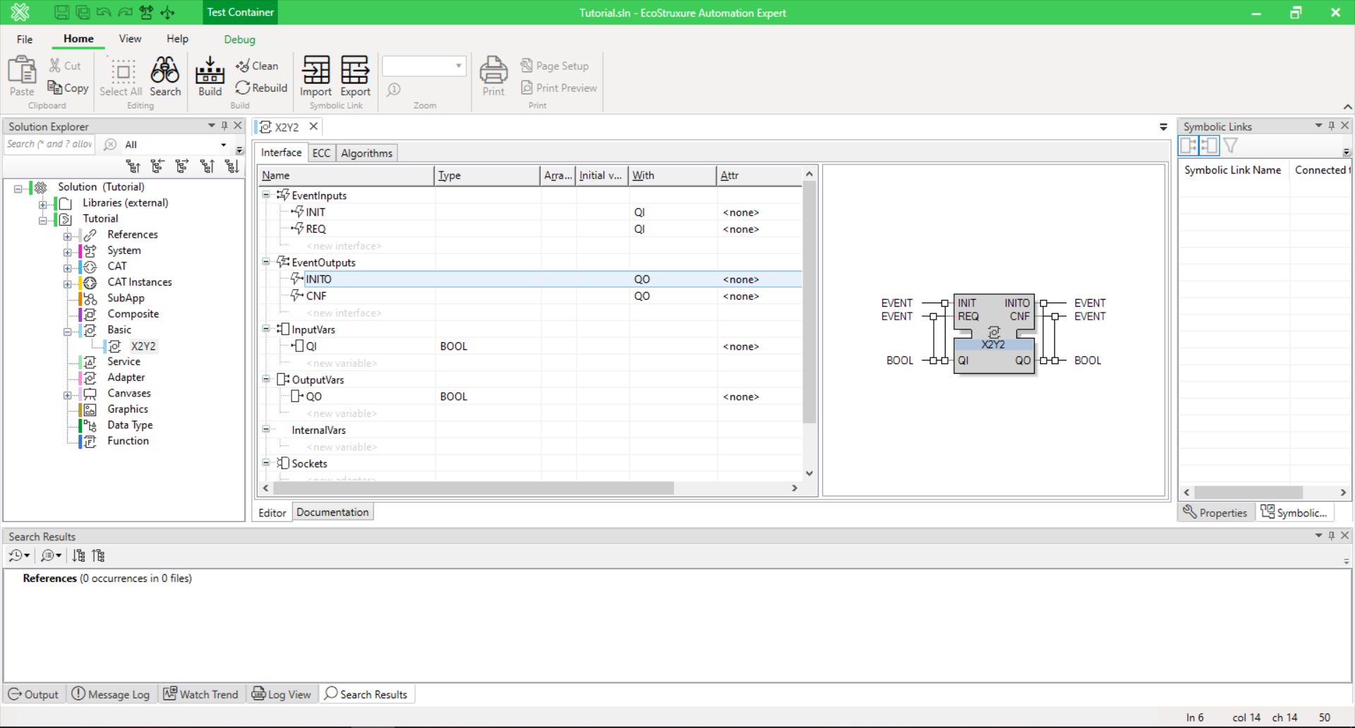
Figure 2(b). Modifying interface of the created FB type.
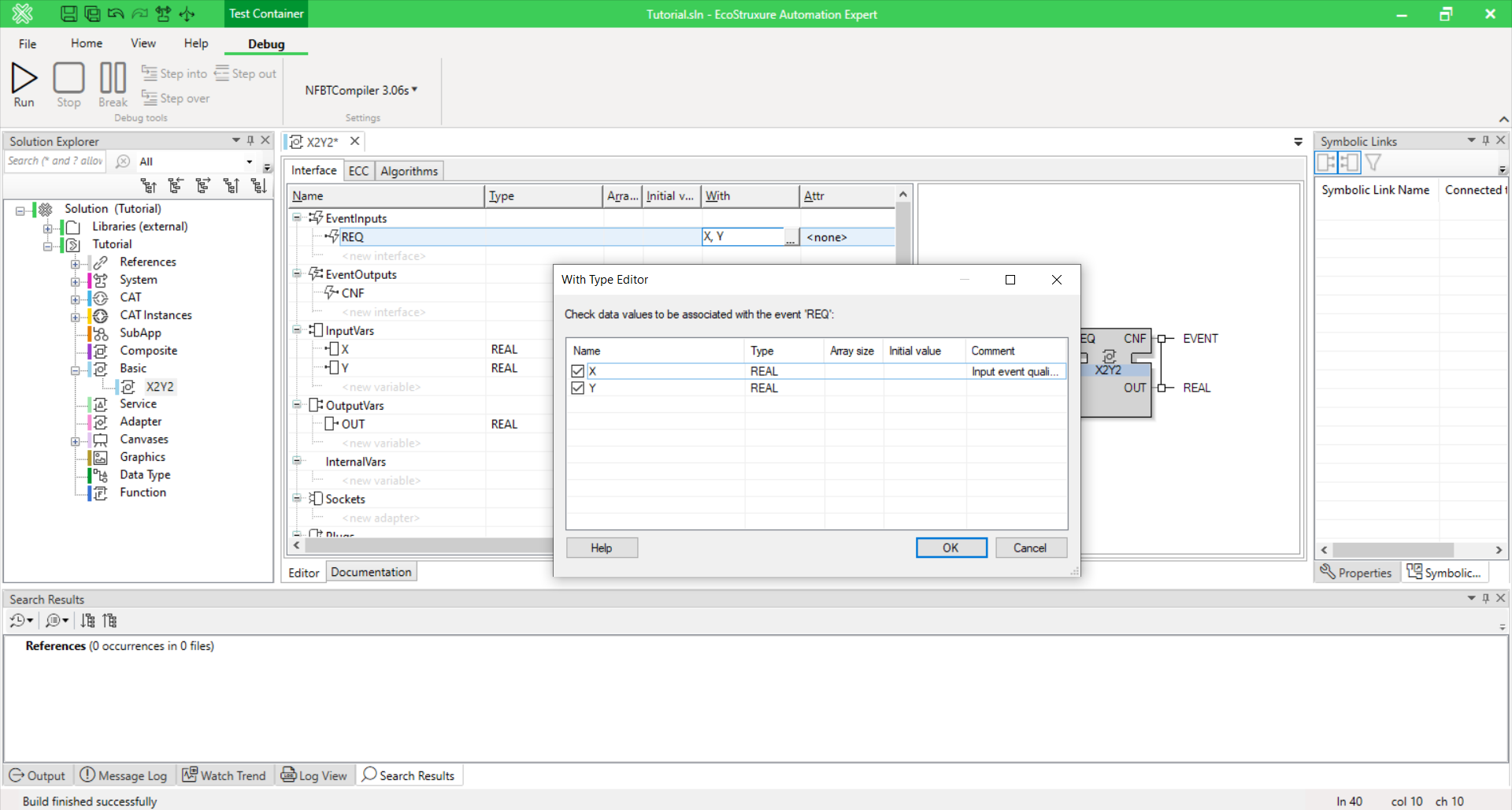
Figure 2(c). Creating association between event ‘REQ’ and input variable ‘Y’.
Now, switch to the ‘ECC’ tab and edit the ECC as shown in Figure 3 (a). You will need to delete the state INIT because in this simple example we don’t need initialization. To do so, hover your mouse over the ‘INIT’ state, right click and select ‘Delete’ from the menu. Alternatively, select the state with a left mouse click and press the ‘Delete’ key. Next, switch to the ‘Algorithms’ tab and delete the algorithm INIT (right click on the INIT tab and select “Delete algorithm”) and edit the algorithm REQ as shown in Figure 3 (b).
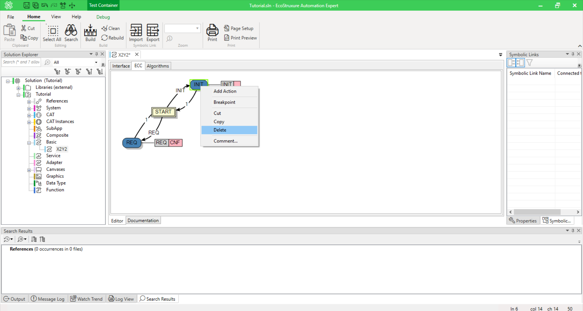
Figure 3(a). Delete state INIT in ECC.
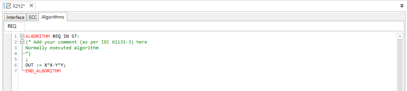
Figure 3(b). Edit the REQ algorithm.
The completed function block can now be tested. From the Menu bar, select Debug tab and click Run (arrow) like shown on Figure 4 (a); the debugging window will then appear, as shown in Figure 4 (b) and to test the function block, you need to assign some values to the data inputs and trigger event REQ by clicking on the corresponding button next to it. After triggering the ‘REQ’ event, the output event ‘CNF’ is triggered (a fulfilled radio button) and the computed value is seen in the OUT field. On the left-hand side, you can see the current state of the ECC. To stop debugging and return to the editing mode, select ‘Stop Process’ from the ‘Debug Menu’.
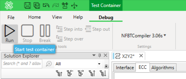
Figure 4(a). Running the debugging process.
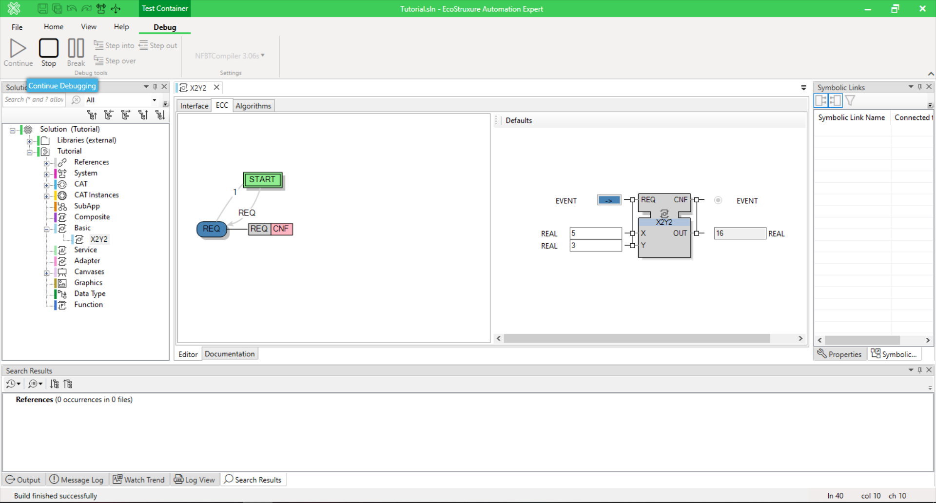
Figure 4(b). Setting values to the inputs of the function block and triggering REQ event.
Now, let us experiment with creating a new FB with more inputs and outputs based on the ‘X2Y2’ we have just created.
Create a new FB type based on an existing one. You need to copy the FB type in the solution tree and then paste it with a different name, for example ‘X2Y2_XYZ’. To copy, go to solution tree, right click on the old FB and select ‘Copy’ from the context menu, Figure 5(a); then right click on ‘Basic’ and select ‘Paste’ as shown in Figure 5 (b).
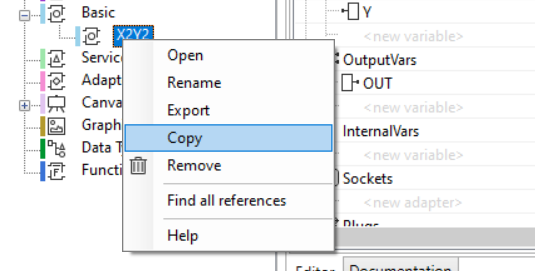
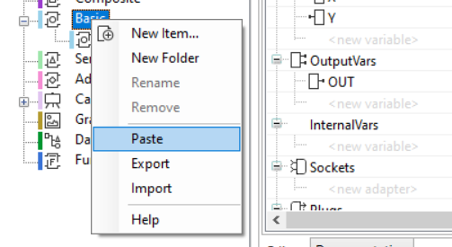
Figure 5(a). Copy FB. Figure 5(b), Paste FB.
Let us do the following modifications in a newly added FB: add a numeric input Z (of type REAL); an event input XYZ associated with X, Y and Z; a data output OUT2 (of type REAL) and an event output CNF2 associated with OUT2 and when the XYZ event is triggered, the FB shall then compute OUT2=X+Y+Z and fire an event at CNF2.
The interface of the new FB type with added inputs/outputs is shown in Figure 6 (a). The next step is to add a new algorithm, ‘XYZ_COMP’. In the Algorithms tab, right click on the existing algorithm ‘REQ’ and select “Add algorithm” (Figure 6 (b)). Enter the name XYZ_COMP in the prompt window and for the algorithm body enter “OUT2:=X+Y+Z;”
Note: the name of the FB type will be updated in the tree only after saving the solution (by Ctrl-S or the save button in the toolbar).
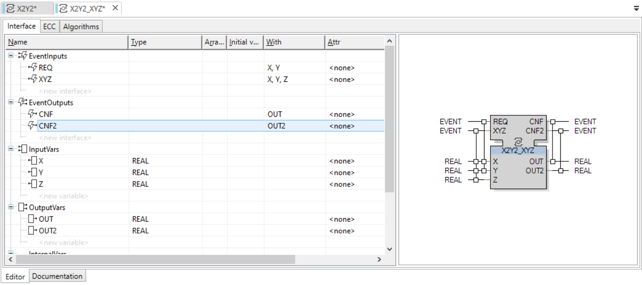
Figure 6(a). Configured ‘FB X2Y2_XYZ’.
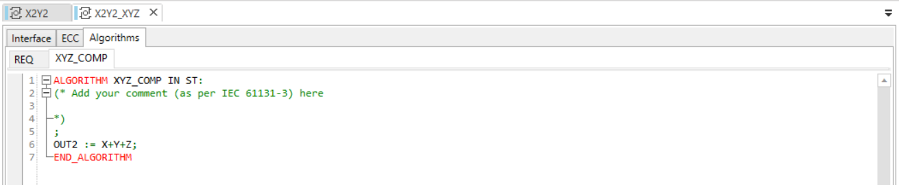
Figure 6(b). Algorithm for ‘FB X2Y2_XYZ’.
The next step is to edit the ECC by adding a new state that will call the algorithm you have just created. Let us create a new state “XYZ_S” by right clicking anywhere blank in the ECC tab, then select “New State” as shown in Figure 7 (a). Editing the ECC is very intuitive, to draw a transition between two states, hover the cursor over the source state and after the cursor has turned into a hand pictogram, hold and drag the left mouse button to the destination state (Figure 7 (b)). To change the condition of the transition, simply double click on the default condition ‘1’ and enter ‘XYZ’ (the input event we created earlier) in the Transition Editor. Create another transition from ‘XYZ_S’ back to ‘START’ with default transition condition ‘1’.
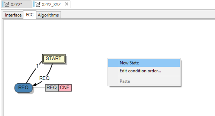
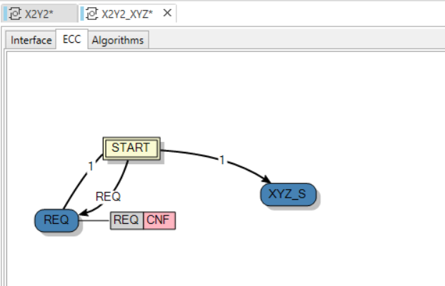
Figure 7(a). Creating new state. Figure 7(b). Making a transition link.
After the new state is created, we need to create a new action in this state in order to call the algorithm ‘XYZ_COMP” and define what output event will then be emitted. All these actions are easily achieved by right clicking on the state and the algorithm/event field associated with it. The ECC should now look like what is shown in Figure 8.
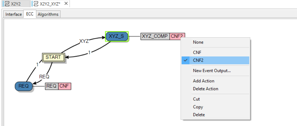
Figure 8. Editing an ECC state.
You can now test this new function block like before using the ‘Run’ option from the ‘Debug’ menu.
Create a composite function block type in EcoStruxure.
Now, let us create a new, composite function block type named X2Y2_CMP as shown in Figure 9. For that, select ‘Composite’ element in the Solution Overview on the left, right click on it and select ‘New Item’. Then you need to perform the same actions as for creating a basic function block by giving it a name and define its interface as shown below.
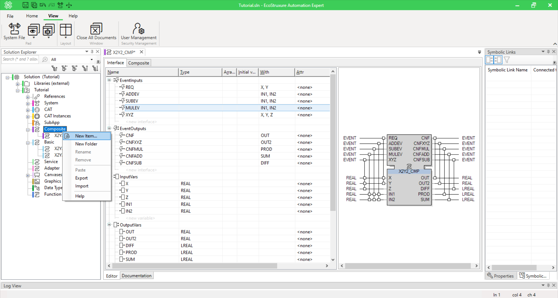
Figure 9. Creating a composite FB and the interface of the X2-Y2 function.
To edit the composite function block body, switch to the ‘Composite tab’. To create new function block instances, either drag the function block type from the ‘Solution Overview’ or right click anywhere blank and use the right click menu as shown in Figure 10 and Figure 12.
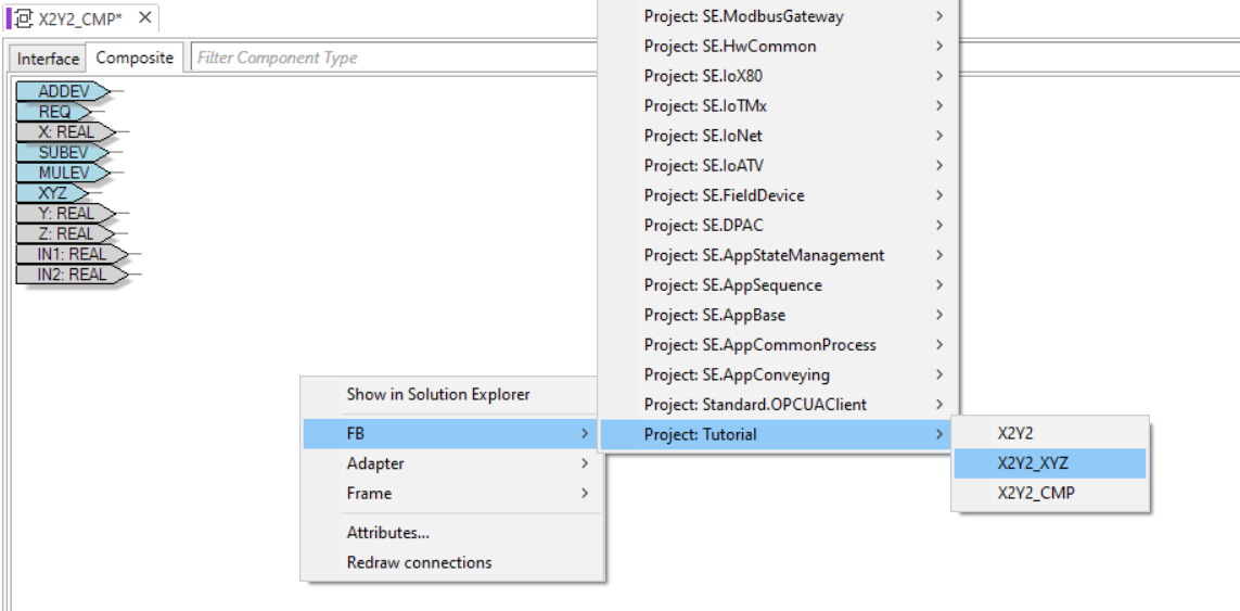
Figure 10(a). Adding self-made FBs into a composite FB network.
For the body of the X2Y2_CMP, add the following FB instances: an ‘ADD’, a ‘SUB’, a ‘MUL’ and an X2Y2_XYZ. Connecting events and data variables of different function block instances to each other can be done simply by dragging a line from the source to destination. To assign a constant value to a data variable, right click on the variable and select “Add Constant” Figure 11(a). The finished FB network should be similar to Figure 11(b). Note that the FB’s of types ‘ADD’, ‘SUB’ and ‘MUL’ can be found in the library shown in Figure 12.
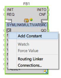
Figure 11(a). Adding constant to a FB input.
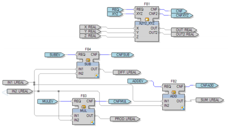
Figure 11(b). Composite Block Network of X2Y2_CMP.
Unfortunately, the testing environment for basic FBs is not available for composite FBs in the current version of EcoStruxure Automation Expert. Therefore, composite FBs can be tested only as a part of applications which will be discussed in the next section.
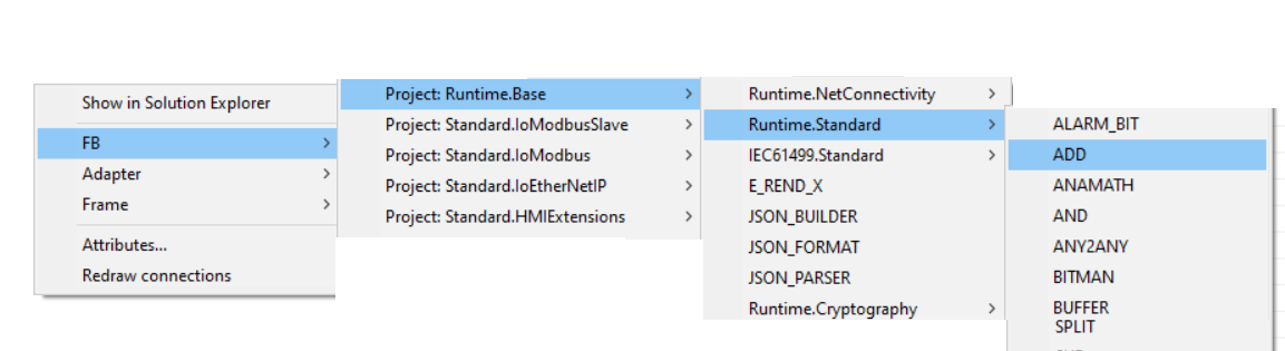
Figure 12. Adding standard FBs into a composite FB network.
Advanced topics of Function Blocks
Creating an application and mapping a FB to a device/resource
As mentioned in the previous section, we cannot test the composite block in the debugger, so we will need to create a function block application and deploy and run it on a device (see section 3.3).
To create a function block application, double click on the ‘APP1’ item under the System node in the solution explorer tree on the left. Then just drag and drop the composite block ‘XYZ_COMP’ from the solution explorer to the canvas in the middle. Right click on the block ‘XYZ_COMP’ and select Mapping>EcoRT_RES0 as shown in Figure 13 to map the FB to a resource.
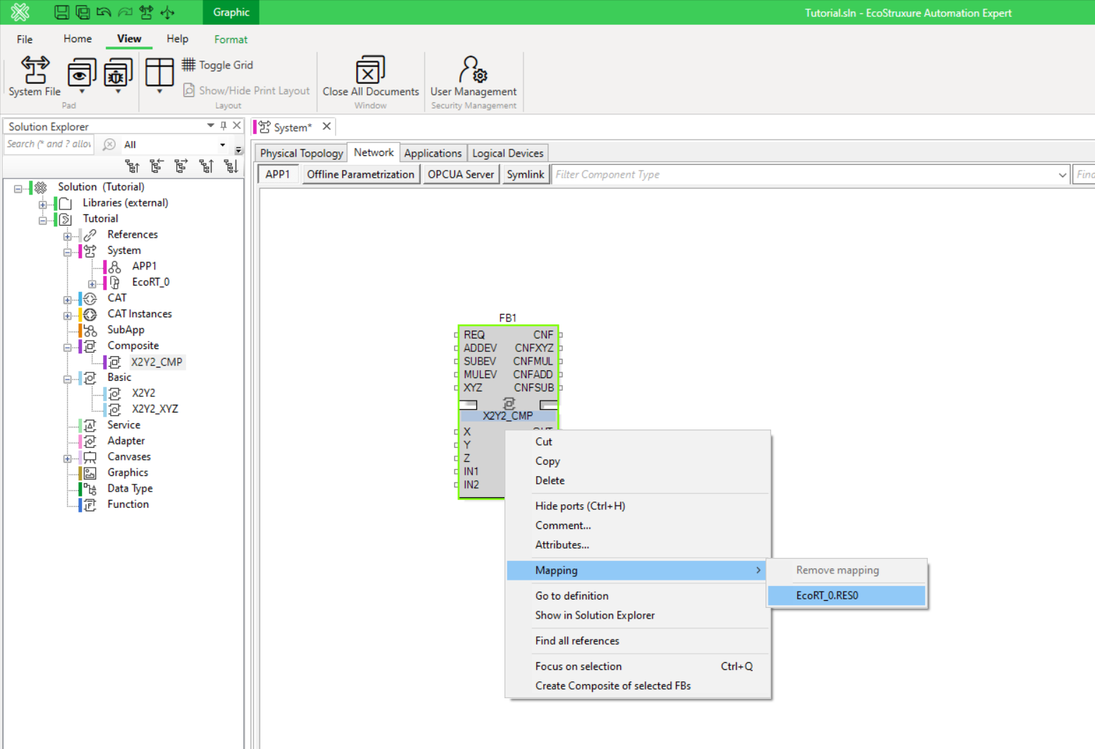
Figure 13. Mapping FBs to a resource.
If we are to create a distributed solution with multiple devices, you can add a new device in the System page in a similar fashion when adding a standard FB. Right click on the list under the Logical Device Name section of the screen and click Add Device. New device will be added as shown on Figure 14 by selecting “SE.DPAC:Soft_dPAC” device type and naming it “EcoRT_1”. After all mappings are completed, follow section 3.1 and 3.3 for instructions on how to deploy and watch/force the events/variables.
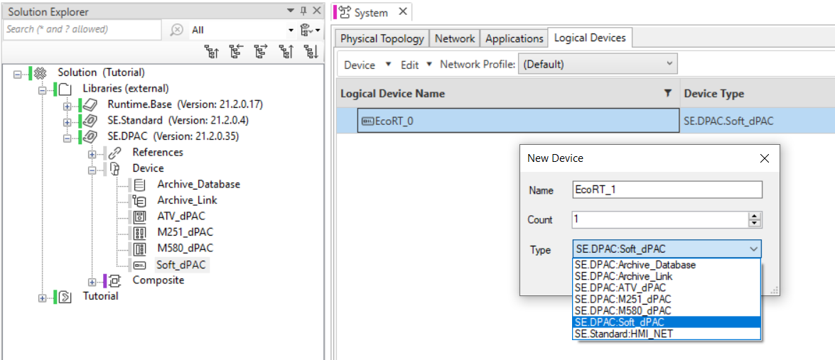
Figure 14. The new device can also be added by dragging Soft_dPAC from the Device list in SE.DPAC located in Libraries section of the Solution Overview to the System window.
Creating an application and mapping a FB to a device/resource
The next lab topic will deal with the FLASHER system. The idea of the distributed FLASHER implementation is shown in Figure 15. Here, the microprocessor of the parameters’ input device reads all the input events and parameter values and then sends them to the recipient devices over the network. Another decision-making device receives these values and generates the values of “on/off” signals for each of the lamps, which are also published to the network. Finally, the output display, which in this case is a block of four LEDs (again with an embedded microprocessor) receives the values and displays them on the LEDs.
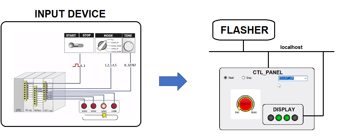
Figure 15. Shifting from 1-device application to 3-device application.
Now, let us follow the instructions on creating a distributed system configuration. Using the unarchive option in Ecostruxure Automation Expert, unarchive the provided in the course material FLASHER.sln.zip solution. Modify the device configuration so that it corresponds to Figure 16.
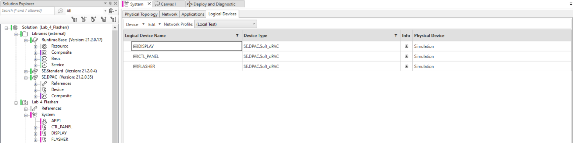
Figure 16. Logical Devices: CTL_PANEL, DISPLAY and FLASHER.
After adding devices, accordingly, save the project so that changes may apply to the rest of the project.
In Logical Devices tab select “Local Test” Network Profile - this allows deployed application to communicate on local machine.
To map different FBs in the application to the three devices, click on the application (APP1) icon in the tree view and follow the similar instruction given in the previous section (Figure 13) and duplicated in Figure 17. The completed mapping of the distributed system FLASHERR is shown in Figure 18.
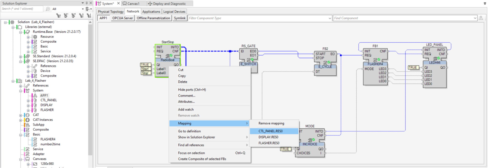
Figure 17. FBs are mapped to corresponding logical devices.
Remember after each mapping, you need to reconnect the necessary INIT event connections to their respective E_RESTART which can be done in the resource page under each device.
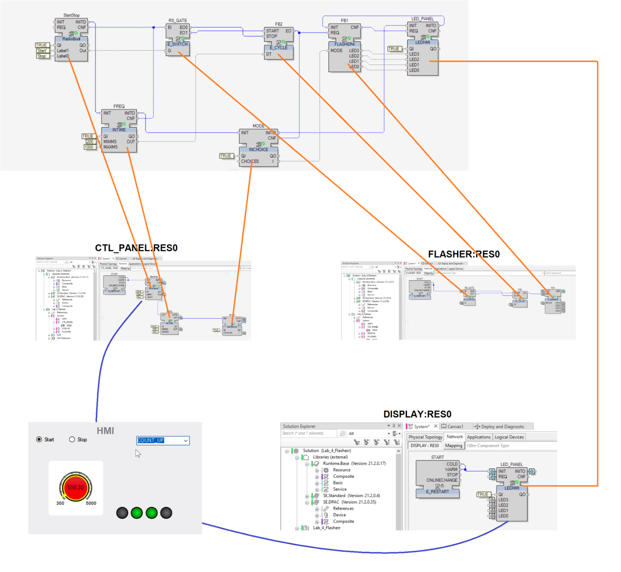
Figure 18. Distribution of the FLASHER application across three devices.
Deployment and Running
To deploy and test the solution on soft PLC running on local machine, do the follows:
-
Again, in the Logical Devices tab, switch to the (Local Test) network profile as in Figure 16.
-
Open the Deploy and Diagnostic window by finding its icon on the top of the EcoStruxure as in Figure 19.
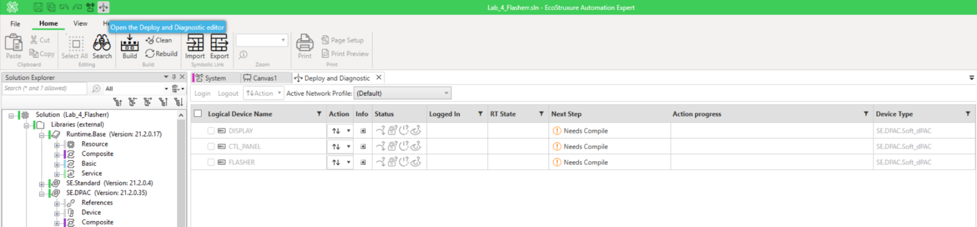
Figure 19. Device list in Deployment and Diagnostic window
-
Set the Active Network Profile to (Local Test).
-
Select all three logical devices and set Action to Compile.
-
For all of them again set Action to Runtime Simulation - Start as in Figure 20.
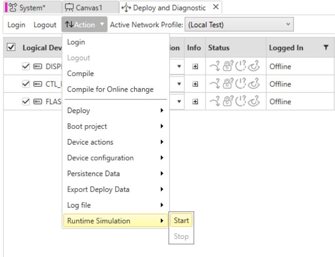
Figure 20. Starting Runtime Simulation
Action Progress status for each device should be set “Runtime Simulation started”.
- Select Action to Login. Situation should be as in Figure 21.
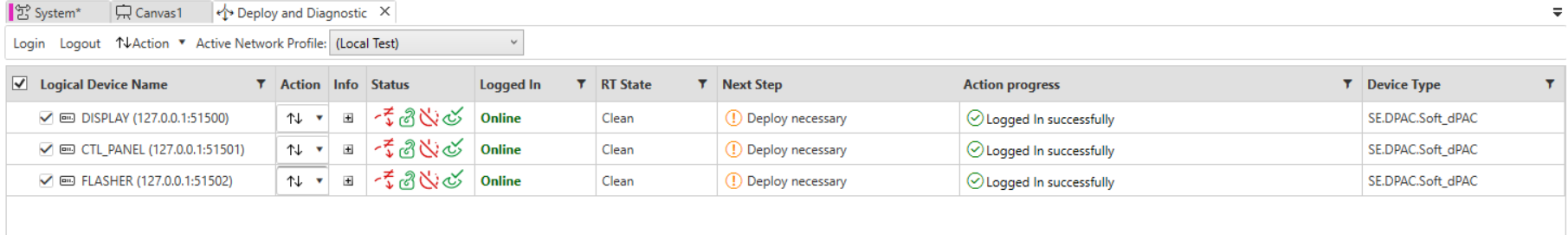
Figure 21. Updated status for devices Logged In status set as Online
- Select Action to Deploy - Deploy and Action to Results would be as shown in Figure 22
It is worth mentioning that every time you want to deploy changes in the project - you have to clean the logical devices with Action - Deploy - Clean.
- Select Action to Device Actions - Run.
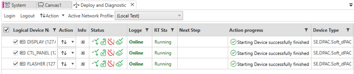
Figure 22. Updated status for deployed application parts for each device
- Start the HMI panel as in Figure 23 (a), authorize using login “DIAS” and password “Dias@2022”. You will see the interface as in Figure 23 (b). If it prompts for username and password, use IEC61499 for username and Iec#61499 for password.
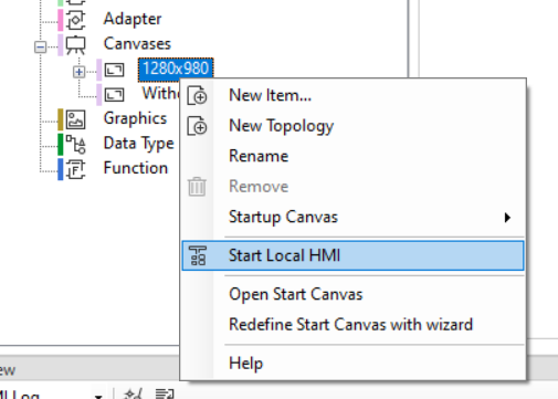
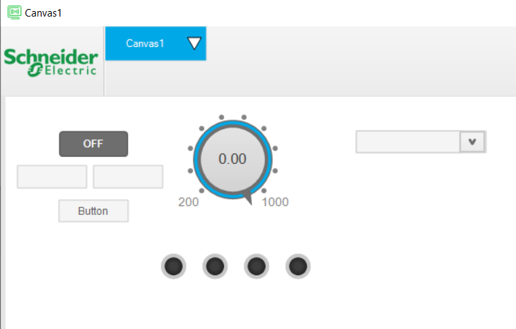
Figure 23(a). Running the HMI. Figure 23(b). HMI screen.
- Watch variables by right clicking on a variable (Figure 24). Try different options in HMI panel and see how variables in the devices change (Figure 25).
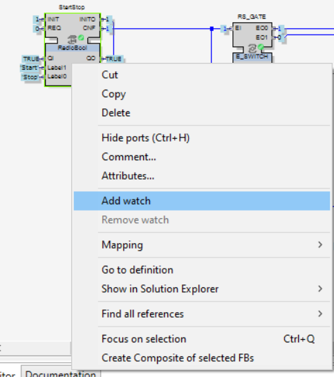
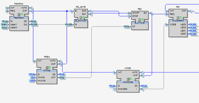
Figure 24. Setting watched variables. Figure 25. Observing values of variables.